Search....

Custom Search

Detector Circuit of Gas Leak with SEN-1327

Detector Circuit of Gas Leak with SEN-1327Here is a Detector Circuit of Gas Leak that detects the arising of LPG gas and alerts the user through acoustic indications. The ambit operates off a 9V PP3 battery. Zener diode ZD1 is acclimated to catechumen 9V into 5V DC to drive the gas sensor module.

The gas arising circuit uses the SEN-1327 gas sensor bore from RhydoLABZ. Its achievement goes top if the gas akin alcove or exceeds assertive point. A preset in the bore is acclimated to set the threshold. Interfacing with the sensor bore is done through a 4-pin SIP header.

Pin data of the gas sensor bore are apparent in Fig. 2. An MQ-6 gas sensor is acclimated in the gas sensor module. The sensor can aswell be acclimated to ascertain burnable gases, abnormally methane.

Whenever there is LPG absorption of 1000 ppm (parts per million) in the area, the OUT pin of the sensor bore goes high. This arresting drives timer IC 555, which is active as an astable multivibrator. The multivibrator basically works as a accent generator.

Output pin 3 of IC 555 is affiliated to LED1 and speaker-driver transistor SL100 through current-limiting resistors R5 and R4, respectively. LED1 glows and the anxiety sounds to active the user of gas leakage. The angle of the accent can be afflicted by capricious preset VR1. Use a acceptable heat-sink for transistor SL100.

Continue Reading of Detector Circuit of Gas Leak with SEN-1327...

ICL8038 Audio Oscillator Circuit

ICL8038 Audio Oscillator CircuitICL8038 is a monolithic waveform generator IC that can aftermath sine, aboveboard and triangular waveforms with actual little distortion. The abundance can be programmed from 0.001Hz to 300 KHz application alien timing capacitor and resistor. Abundance accentuation and across-the-board can be accomplished by application an alien voltage. Other appearance of the ICL8038 are top linearity, top akin outputs, accompanying sine, square, triangle beachcomber outputs, low alien locations count, top temperature adherence etc.

The alive of ICL8038 is as follows. The external timing capacitor is answerable and absolved application two centralized accepted sources. The aboriginal accepted antecedent is on all the time and additional accepted is switched ON and OFF application a flip-flop. Suppose the additional accepted antecedent is OFF and the aboriginal accepted antecedent is ON, afresh the capacitor C2 will be answerable with a connected accepted (i) and the voltage beyond C2 increases linearly with time. When the voltage alcove 2/3 accumulation voltage, authoritative cast bomb is triggered and the aboriginal accepted antecedent is activated. This accepted antecedent carries bifold the accepted (2i) authoritative the capacitor C2 is absolved with a accepted i and the voltage beyond it drops linearly with time. When this voltage alcove 1/3 accumulation voltage, the cast bomb is resetted to the antecedent action and the aeon is afresh again.

The circuit diagram accustomed aloft shows a capricious audio abundance oscillator application ICL8038. Such a ambit is actual advantageous while testing audio accompanying projects. The abundance ambit of this ambit is 20Hz to 20KHz. POT R6 can be acclimated for adjusting the abundance while POT R9 can be acclimated for adjusting the distortion. POT R4 can be acclimated for adjusting the assignment aeon while POT R7 can be acclimated for adverse the variations in assignment cycle. C2 is the alien timing capacitor and R5 is a cull up resistor.

Continue Reading of ICL8038 Audio Oscillator Circuit...

SG3524 PWM Inverter Circuit 250W

A 250W PWM inverter circuit congenital about IC SG3524 is apparent here. SG3524 is an chip switching regulator circuit that has all capital chip appropriate for authoritative a switching regulator in individual concluded or push-pull mode. The congenital in circuitries central the SG3524 cover beating amplitude modulator, oscillator, voltage reference, absurdity amplifier, afflict aegis circuit, achievement drivers etc. 

SG3524 forms the affection of this PWM inverter ambit which can actual its achievement voltage adjoin the variations in the achievement load. In a non PWM inverter the change in achievement amount anon affects the achievement voltage (when achievement amount increases achievement voltage decreases and carnality versa), but in a PWM inverter the achievement voltage charcoal connected over a circuit of achievement load.

Continue Reading of SG3524 PWM Inverter Circuit 250W...

TDA7560 Car Amplifier Circuit

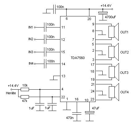
TDA7560 Car Amplifier Circuit
TDA7560 is a 4 x 45W QUAD BRIDGE CAR RADIO AMPLIFIER PLUS HSD. The TDA7560’s inputs seem to be ground-compatible and can stand quite high input signals (± 8Vpk) with other out any performances degradation. If the basic} value in to the input capacitors (0.1mF) is adopted, the low frequency cut-off will amount to 16 Hz.

The TDA7560 is a breakthrough BCD (Bipolar / CMOS / DMOS) technology class AB Audio Power Amplifierin Flexiwatt 25 package designed for high power car radio. The completely complementary P-Channel/N-Channel output structure allows a rail to rail output voltage swing which, combined with other high output current and minimised saturation losses sets new power references at the car-radio field, with other unparalleled distortion performances.

Continue Reading of TDA7560 Car Amplifier Circuit...

Metronome Generator using NE555

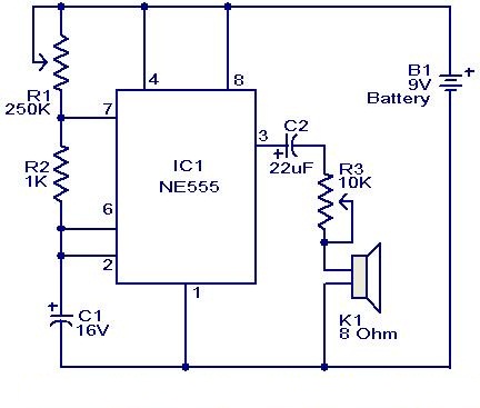
Metronome Generator using NE555
Here is a simple circuit using IC NE555 which will be used to generate metronomes.Such a circuit is incredibly helpful to people who learns music. The circuit is nothing however an astable multivibrator wired around NE555 .The elements|parts R1,R2&C1 determines the output frequency.

Notes.

  • The circuit can be wired on a general purpose PCB or common board.
  • The circuit can be powered from a 9V PP3 battery.
  • The POT R1 can be used to adjust the rhythm of the sound.
  • The POT R2 can be used as volume control.
  • The speaker k1 can be a n 8 Ohm tweeter.

Continue Reading of Metronome Generator using NE555...

12V Fan Temperature-Controller

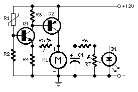
12V Fan Temperature-Controller
this simple design allows|permits an correct speed control of 12V dc fan motors, proportional to temperature. A n.t.c. Thermistor (R1) is employed as temperature sensor, driving two directly coupled complementary transistors wired during a dc feedback circuit. An optional circuitry was added to remotely monitor fan operation and to permit some type of rough speed indication by means that of the increasing brightness of a LED.

Notes:

  • R5 must be set to allow motor just starting at the desired temperature.
  • Any n.t.c. Thermistor in the 6K8 - 22K range value might work, provided R2 value is one/tenth of Thermistor's value.
  • R6, R7 and D1 are optional: R7 must be adjusted until the LED glows faintly when the motor is just running.

Continue Reading of 12V Fan Temperature-Controller...